
I prefer using old school methods and simple tools. I want to build this frame like the guys did back in the '60s, who started the whole chopper movement. I found this amazing website for reference that is full of all of this motorcycle wisdom from the ages www.chopperhandbook.com to help me achieve this. I don't have a fancy frame jig or access to a machine shop with all the CNC equipment, just my home garage, a welder, and an assortment of hand tools. I want this frame to look handmade and vintage, but be sturdy and well built. It has to look right, feel right, and ride right. No billet. No compromises.
I thought I would document the process, it should be an interesting journey...
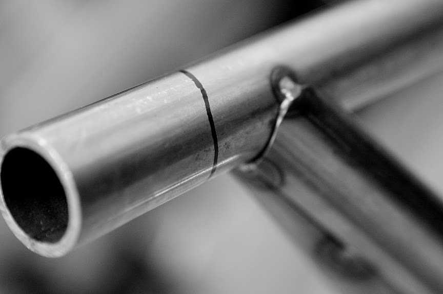
Rough Cutting the Frame Parts
I finally got around to starting my frame build today. I had to finish the chop on my lift first, and a couple of other projects. It's hard to believe I am going to be riding this pile of tubes someday soon. This represents 38' of 1.25 x .120 ERW mild steel structural tubing, and one short piece of 1" x 2" x .120 rectangle tube. It came to about $65 worth of material. What an inexpensive frame! Now I just have to put it together.

I have the rough measurements for the frame parts that I will cut now before I begin fitting them together:
These parts are 1.25" x .120 round tube:
2 Down tubes 84"
2 Wishbones 38"
1 Backbone 35"
1 Seat post 22"
3 Wishbone crossmember/spacers 12"
These parts are 1" x 2" x .120 rectangle tube:
2 Seat post/ transmission crossmember 12"
Time to start chopping tube.

This is what we end up with.

Now the fun really begins. I am going to make the bends in the downtubes and the wishbones first.
Get Bent
The next step is to bend the frame parts that need bending. I'm starting with the wishbones. They are pretty simple and require just one 25 degree bend. I marked the tube, fed it into the bender, and set the marker.

here goes...

Here are the frame parts for the top assembly. Now I just have to bend the lower rails.

Coping the Frame Parts
Now it's time to make all these parts fit together. Unfortunately I have to do it the hard way. I can't really afford an end mill for this project so I will cope all the tube ends by hand with a grinder. I found a great web site with a tube coping calculator Metalgeek.com . There are some tough angles on the frame so I found the coping calculator a big help.
So you just enter the tube dimensions and angle of the cut and you get a file to print and cut out. Then wrap the pattern around the tube and mark your cut line. I thought I would start with the fender crossmember. In case I screw up it's a short piece of tube to replace.


Cut to length

rough shape on the chop saw

My grinding wheel is worn out and pretty rounded which worked great for shaping the tube.

Looking pretty good, now check to make sure it's square

Close, just some final touch up with the die grinder


Nice fit

The seat post shouldn't be too difficult. The top has a 98 degree cope. I just have to make sure the top and bottom angles are facing the same direction.

The bottom has a 73 degree flat angle.


Looks good

This angle is going to be hard. I saved it for last. This is the connection where the wishbone meets the backbone. It's a 26 degree angle. I'm wishing I had an end mill right about now.


This one took a while to get right. Definitely the hardest cut on the frame...until I got to the neck bracing.

Petty close. A little fine tuning with the die grinder ought to do it.

Fitting the Frame Parts
Now that all the frame parts are bent and coped it's time to start fitting them together. I'm going to do as much as I can without the aid of a frame jig. First I will tack together the top assembly: backbone, wishbones, and fender crossmemeber. To do this I made a template on cardboard so I could make sure all the parts were square and parallel and in the right place before I tacked them together.

It is important to have a qualified assistant to help in the shop, especially when there's critical layout happening that requires accuracy. Some bike builders have Pit Bulls for shop pets, somehow I ended up with cats. They don't even flinch when I weld, grind, and hammer.

All set up on the template and ready for first tack welds.

Tacked together top assembly

Seat post


I had to cope the ends of the seat post crossmember before tacking the seat post on.

I bent the lower rails according to plans, but for got to document the progress. Trust me, it was exciting.
With duct tape, clamps, and bungee cords I held the frame parts together to check for proper fit. It's starting to look like a frame now!

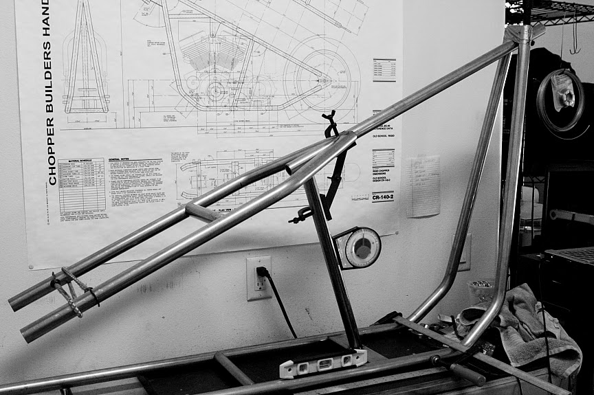

Fortunately everything is within specs so far. I only have two more bends to make in the lower rails and two more coping joints: the downtube/backbone joint and the steering head/backbone joint.
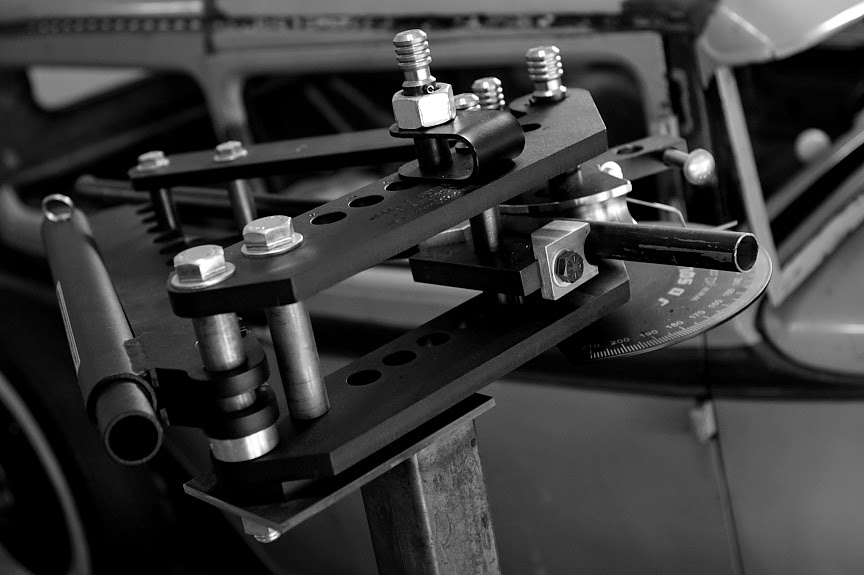
Time For a Frame Jig
You can only go so far without a little help. I'm tired holding frame parts together with duct tape, bungee cords, and clamps. And I've only got two hands so I had to stop for a minute and work on a jig to hold everything in place while I work on the frame. I am going to work on the down tube/back bone joint next so I will start with that fixture. I can add other fixtures as I need them later. I got the plans for this jig from www.chopperhandbook.com .

It is so much easier with the jig holding parts in place with no tape or bungee cords!

Down Tubes Meet the Backbone
Next I need to join the tops of the down tubes where they meet at the steering neck. The idea is to join the two tubes so that they make a single tube of the same diameter at the top. So you can cope that joint for the back bone to set in place. I marked long angles starting from the center of the top of the down tubes.

This is the first rough cut in the down tube. I used a cut off wheel on the 4" grinder. It looks bad now, but I will fix that as the two tubes come together. I ground of a little at a time until they were even an touching each other flat at the joint.

Here they are getting close...

...Top view.

Now I have a nice tight fit and the top of the tubes are about the same diameter as a single tube. Next step is top cope out a notch for the back bone to set in.
So I set the back bone in place and marked where they intersect the down tubes.

I found the center of the back bone from the side and the intersection is marked on the down tubes.

I started with a cutting wheel to remove bigger chunks of the notches and then moved to a grinding wheel to slowly enlarge the notches evenly on both sides.

This part is kind of tricky so I was careful to not remove too much material. I would hate to have to cut and bend new down tubes after all that work.

In this shot I'm getting pretty close. I left the tops of the down tubes on to make it easier to see if they were even on both sides...

...Top view.

The fit is pretty tight here. Now I can cut off the excess on the top.

This is the rough cut. I will round those out to make a nicer looking joint.


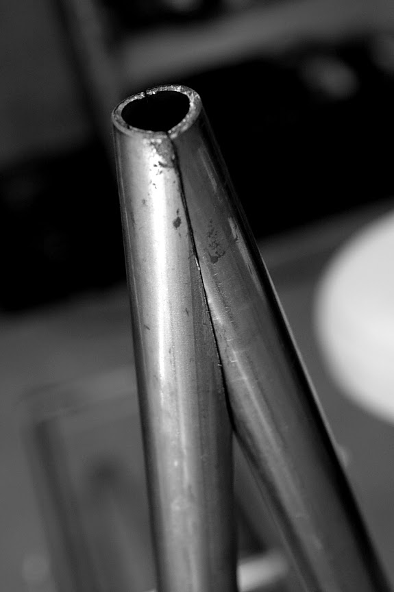
Here is the finished joint. looks nice and tight.


Top view of the finished joint. Now it's time to tack it together.

Final Bends in the Lower Rails
Before I could tack the down tubes in place I needed to make the final bends where the lower rails meet the axle plates.

For some reason this bend was especially tricky to get right. Now that we know the angle of the down tubes we can make the upward bend in the lower rails. You have to find the new top center of the rails and set them up accordingly in the bender. I measured carefully, but the bends were still a little off. I had to manualy adjust the bends with leverage from a long pipe to make them so they were ready for axle plates.


Axle Plates
I built this axle fixture to locate the axle plates in the proper position. I used 3/4 threaded rod so I could bolt them in place. Here the wishbones and lower rails are still a little long. I wanted to look at the axle plates in place before I cut them to their final length.

I had to tweak the wish bones/ lower rails a little with some leverage to line them up. It was difficult getting those last couple of bends perfect.

This is my favorite template material - beer box. It is just the right weight; stiff enough to hold shape, yet thin enough to cut with scissors.


This is a rough estimate on the shape of the plates. I ended up cutting a bigger template for the final shape.

With the rails bent up into position it is really starting to look like a frame.

I wanted to double check the centerline of the frame was lines up with the CL of the jig before I set the axle plates.


This si the final shape of the axle plates. Now I know where to make the final cuts on the tubes. I just carefully used a cutting wheel on my grinder for this step.


I transferred the pattern from the template onto the 3/8" plate and cut them out with the cutting wheel.

I cleaned up the shape with the bench top grinder and then sander.Then I found the center of the adjustment slots and drilled a hole for the axle to locate the axle plates.

Here is the plate bolted into position on the outside of the frame.

The wishbones/lower rails are now cut to final length.

I drilled two more holes for the front and rear of the adjustment slots in each plate. Now I can cut the slots in the tubing for the axle plates to fit into. I marked four two inch slots in the center of the tubing ends. I cut these slots using the cutting wheel on the 4" grinder. I got so busy working on this step I forgot to document progress, so no pictures.


I drilled a few more holes to aid in cutting out the rest of the adjustment slots. I did this before tacking the plates in position. It was easier to work on the slots out of the frame.

I double checked all my measurements again and tacked the axle plates into their slots.


Axle plates are now tacked into position. I will check all measurements again before I fully weld everything.

Steering Neck
Now I get to decide what the steering angle is going to be. I don't want this frame to be too raked out and compromise handling quality. I'm thinking 32 degrees will be a good balance between looks/handling.

This is the tubing I will use for the steering neck. It's machined from American DOM tube, 2" O.D. X .344 wall(1 5/16" I.D.) X 5 5/8 long. I purchased this from www.ratholecycles.com .

I downloaded a coping template from metalgeek.com . The angle came out to be 80 degrees


I marked a center line on the top tube to orient the cut line.

I made the rough cut with a cut off wheel...

...then I cleaned it up with the grinding disc.

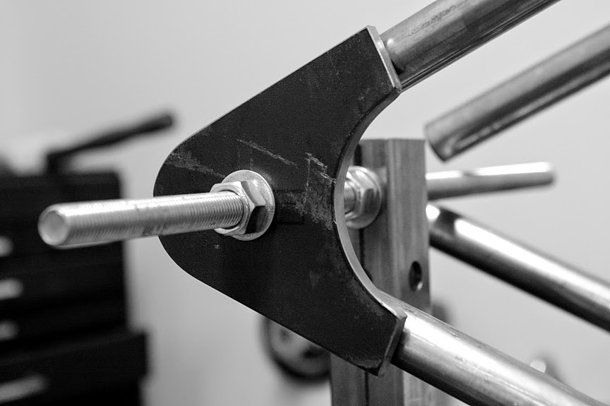
I used a 7' piece of leftover 1.25 tubing to line up the neck with CL of the frame. After I lined it up and set the rake I tacked it in place.

I rechecked all the measurements and tacked it a few more times.

I decided to use a slightly unconventional neck gusset/brace set up. I like the look of the lines better this way. The two tubes are parallel to the ground and lower rails.

I will check all measurements one last time and then weld up my masterpiece.

The frame blocked up to ride height on a 16" x 5.0" tire...

Jerry this is freaking awesome! Nice one dude.
ReplyDeleteThanks, it was a fun project. Now I just need to make a motorcycle out of it!
ReplyDelete